Photovoltaic degradation is an important aspect to consider for system design and installation. Over time, factors such as weather and UV exposure contribute to solar cell performance decline. By better understanding degradation effects and contributors, safeguards and technology enhancements can potentially be considered for performance improvements.
Two key components to monitor, tied to effectively understanding degradation, are DC input voltage and current to the inverters. This must be measured for two reasons. First, understanding the DC performance allows the effect of inverter efficiency to be removed from the degradation data. Second, the inverter technology itself can be better evaluated, as the DC measurements allow for the characterization and understanding of inverter efficiency, key to overall system performance.
What solutions are there?
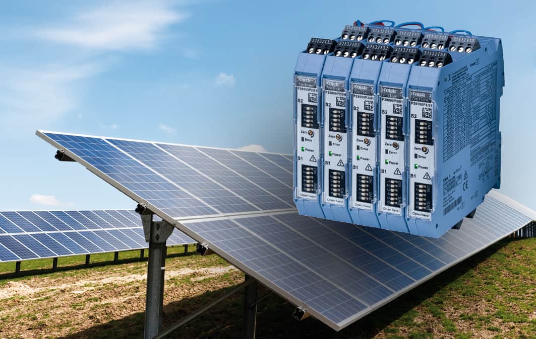
Electrical measurement solutions from Knick Interface, such as the P29000 transducer series, are good solutions to consider for monitoring of DC input voltage and current to PV inverters. They have proven to bring value, many times over, in PV applications globally.
The P29000 measures DC voltage to 1000 V. A typical PV system of 30kW could see voltage signals fluctuate between 0 and 500 VDC, with a level such as 320 VDC seen during normal operation. This makes the input range of the P29000 more than capable of handling the demands of the application. Its measurement error of no more than 0.2% ensures that accuracy of the PV input voltage data is maintained. This accuracy exceeds the requirement set by IEC 61724-1:2017, which defines standards for PV monitoring systems. (Class A precision per IEC 61724-1:2017 calls for an uncertainty in measurement of <= 2% to be maintained.) In addition to satisfying the IEC standard, the P29000 is also UL listed, which is typically a requirement PV system builders and owners need or prefer to maintain with integral components.
Easy integration thanks to large output selection
With its flexibility and options associated with output selection, the P29000 makes it easy to integrate into existing control or data acquisition systems. Voltage input ranges, in addition to desired outputs such as 4-20 mA and 0-10 VDC, are selectable via dip switches on the device. Additional flexibility is provided by its onboard 20 – 253 VAC/DC universal power supply, and din-rail mountable 17.5 mm housing.
For measurement of DC current, the P29000 performs this by way of shunt voltage. A shunt resistor is used in conjunction with the transducer, and sized to provide a standard mV output at the amperage level seen in the application, i.e. 0-50 mV at 0-100 A. This shunt mV is then fed as an input to the P29000, where it can then be used to easily calculate current, as the relationship is linear. The same quality, level of approvals, and flexibility is available with P29000’s designed for both DC voltage and current measurements.
Electrical system safety is also present with the P29000 series, through complete galvanic isolation, also known as working voltage, at 1000 VAC/DC. This means the input, output, and power supply channels are all electrically isolated by way of transformers. Test voltage isolation for the P29000 is even higher, specified at 5.4 kVAC across input and output/power supply. By having this isolation in place, equipment protection concerns associated with voltage spikes can be minimized. Often, this brings peace of mind to PV array installations.
Return on Investment
- High operational safety and accuracy through measurement and electrical isolation up to 1000 V AC/DC and test voltage to 5.4 kVAC
- Satisfies important requirements of the solar industry, including UL product certification and Class A precision per IEC 61724-1:2017
- Value shown through flexibility with calibrated range selection, onboard universal power supply, and din-rail mountable 17.5 mm housing.
Reference: "Written by Steve Allard General Manager at Knick Interface LLC, USA”

